New to the ESP32-WROOM-32? You’ve come to the right place! The ESP32-WROOM-32 is a versatile, low-cost, and energy-efficient System on a Chip (SoC) module developed by Espressif, featuring built-in Wi-Fi, Bluetooth, and Bluetooth Low Energy (BLE) capabilities. With its powerful dual-core processor, integrated antenna, and ample GPIO pins, it’s perfect for both beginners and advanced developers looking to build robust IoT projects. If you’ve previously worked with the ESP8266, you’ll appreciate the ESP32-WROOM-32’s enhanced performance and extensive features.
What is ESP32?
The ESP32 is a series of highly-integrated microcontroller chips developed by Espressif Systems, widely used in IoT (Internet of Things) projects and embedded applications.
Why are they so popular? Mainly because of these impressive features:
- Low-cost: An ESP32 module typically starts at just around $6, making it very affordable and accessible to hobbyists, students, and professional developers alike.
- Low-power consumption: The ESP32 consumes significantly less power compared to many other microcontrollers, and it supports advanced power-saving modes such as deep sleep, ideal for battery-operated devices.
- Built-in Wi-Fi: ESP32 modules have integrated Wi-Fi functionality, allowing devices to easily connect to the internet (station mode) or create their wireless networks (access point mode). This makes them perfect for IoT, smart home, and automation projects where wireless communication is essential.
- Bluetooth capabilities: The ESP32 doesn’t just support Wi-Fi; it also offers Bluetooth Classic and Bluetooth Low Energy (BLE), expanding its application range in wireless sensor networks, wearable devices, and mobile connectivity solutions.
- Dual-core processing: Most ESP32 models feature dual-core processors, equipped with two Xtensa 32-bit LX6 microprocessors (core 0 and core 1), enabling efficient multitasking and improved processing speed for complex tasks.
- Rich peripheral interfaces: With the ESP32, you have access to a comprehensive set of input/output peripherals such as capacitive touch sensors, analog-to-digital converters (ADCs), digital-to-analog converters (DACs), UART, SPI, I2C, PWM outputs, and much more. This versatility allows for extensive interactions with external sensors and actuators.
- Arduino compatibility: Those familiar with the Arduino programming environment will find the ESP32 easy to use, as it supports programming through the Arduino IDE. This makes transitioning from Arduino boards to the ESP32 straightforward.
- MicroPython support: Additionally, the ESP32 is compatible with MicroPython, a streamlined implementation of Python 3 tailored specifically for microcontrollers and embedded devices. This simplifies development and speeds up prototyping for those comfortable with Python.
ESP32 Specifications
If you’re looking to dive deeper into the technical specifics of the ESP32, here’s a detailed overview of its core specifications:
Wireless Connectivity:
- Wi-Fi: High-speed connectivity supporting up to 150 Mbps (HT40 mode).
- Bluetooth: Supports Bluetooth Classic and Bluetooth Low Energy (BLE), ideal for various wireless IoT applications.
Processor:
- Dual-core Tensilica Xtensa LX6 microprocessor with 32-bit architecture, operating frequencies selectable at either 160 MHz or 240 MHz.
Memory:
- ROM: 448 KB for booting and essential firmware functions.
- SRAM: 520 KB for program data and instruction storage.
- RTC Fast SRAM: 8 KB, accessible to the main CPU during wake-up from deep sleep.
- RTC Slow SRAM: 8 KB, accessible by the ultra-low-power co-processor during deep-sleep mode.
- eFuse Memory: 1 Kbit total, with 256 bits reserved for system use (like MAC address and configuration settings) and 768 bits available for custom applications (such as Flash Encryption and Chip Identification).
- Embedded Flash: Internally connected flash memory available in select modules:
- ESP32-D0WDQ6, ESP32-D0WD, and ESP32-S0WD: 0 MiB (external flash required).
- ESP32-D2WD: 2 MiB onboard flash.
- ESP32-PICO-D4 SiP module: 4 MiB onboard flash.
Power Management:
- Low-power design enables the usage of specific peripherals (like ADC conversions) even in deep-sleep mode, making it ideal for battery-powered projects.
Peripheral Interfaces:
- Comprehensive DMA-enabled peripheral interfaces, including:
- Capacitive Touch sensors
- ADC (Analog-to-Digital Converter)
- DAC (Digital-to-Analog Converter)
- UART (Universal Asynchronous Receiver/Transmitter)
- SPI (Serial Peripheral Interface)
- I²C (Inter-Integrated Circuit)
- I²S (Integrated Interchip Sound)
- PWM (Pulse-Width Modulation)
- RMII (Reduced Media-Independent Interface for Ethernet)
Security Features:
- Integrated hardware acceleration for AES encryption, as well as SSL/TLS protocols, enhances secure communications for connected applications.
For more detailed specifications, you can always refer to the official datasheet provided by Espressif https://www.espressif.com/en/support/documents/technical-documents
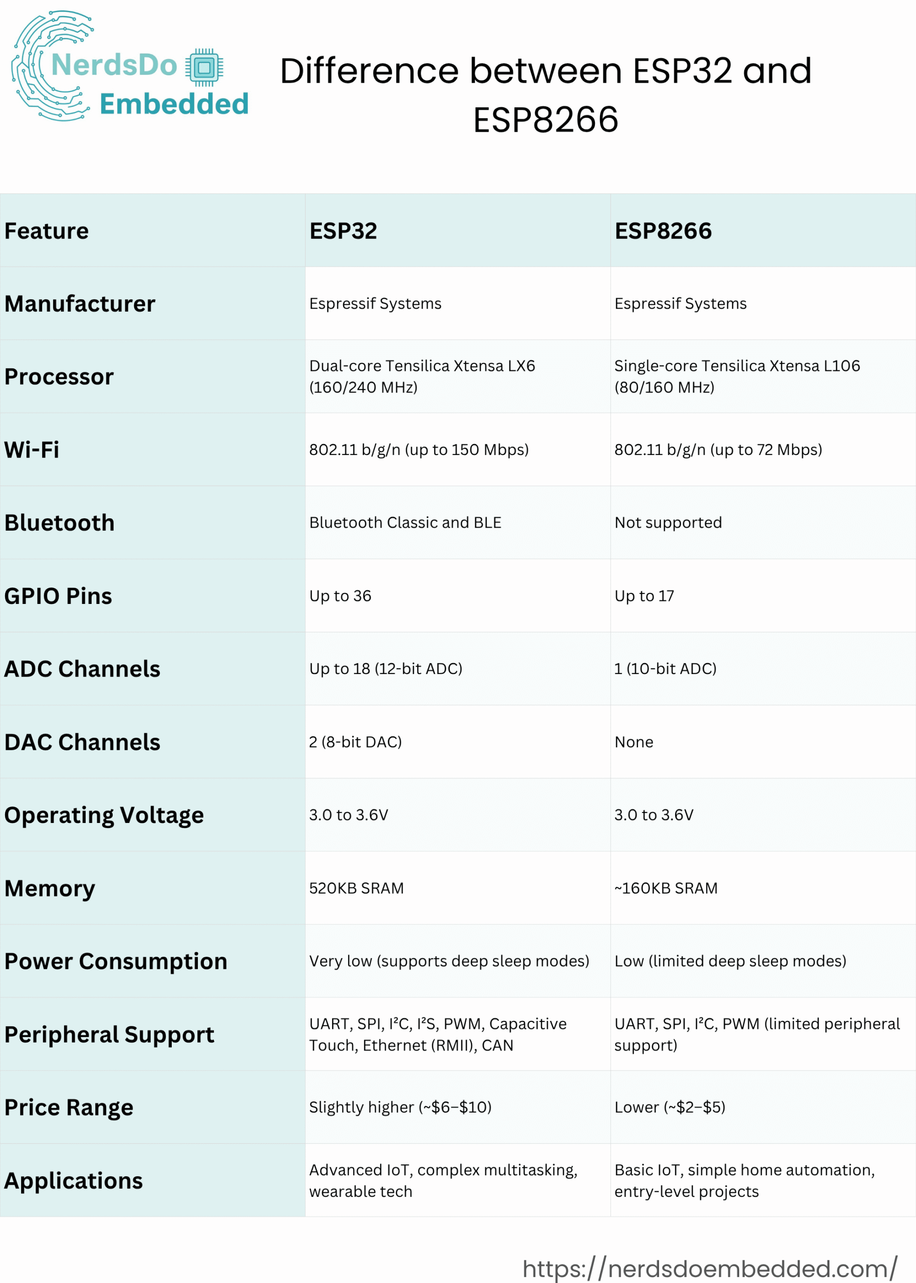
Difference between ESP32 and ESP8266 nodemcu
The ESP32 is the next-generation upgrade to the popular ESP8266, offering enhanced processing power, additional features, and broader connectivity options. While the ESP8266 continues to be a reliable choice for simpler IoT applications and beginner-friendly projects, the ESP32’s advanced capabilities make it ideal for more complex tasks, multitasking, and future-oriented developments.
If you’re new to IoT development or planning sophisticated projects, we recommend choosing the ESP32. However, if you already own an ESP8266, it remains an excellent and affordable option, benefiting from strong community support and ample resources suitable for a wide range of DIY projects
To know more about ESP8266 NodeMCU, refer to the link: https://nerdsdoembedded.com/esp8266_nodemcu/getting-started-with-esp8266-nodemcu/
ESP32 Development Boards
ESP32 typically refers to the standalone ESP32 chip, but the term is commonly used to describe ESP32 development boards. Working directly with the bare ESP32 chip can be challenging, especially if you’re new to electronics or just getting started with prototyping and testing. That’s why ESP32 development boards are so popular—they simplify the entire development process.
ESP32 development boards integrate all necessary components, including voltage regulators, programming interfaces, USB connectivity, and dedicated GPIO pins, making it easy to connect various sensors and peripherals. These boards typically come equipped with built-in LEDs for status indication, onboard antennas for Wi-Fi and Bluetooth connectivity, and user-friendly features that significantly streamline your projects. Additionally, specialized ESP32 boards like the ESP32-CAM include cameras, displays, or specific sensors, making them ideal for advanced applications like video streaming, image processing, and IoT projects.
How to Choose an ESP32 Development Board?
When browsing online for an ESP32 development board, you’ll quickly realize there are many variants available—each with unique features, sizes, and capabilities. While all of them are built around the same ESP32 chip, not all boards are created equal. Choosing the right ESP32 board for your project depends on your specific requirements and use case. Here are the key factors to consider:
1. USB-to-Serial Interface and Voltage Regulator
Most development boards include a USB-to-UART converter and an onboard voltage regulator. These components make it easy to program the board and power it via USB. Without them, you’d need external tools just to upload code or provide stable power.
2. BOOT and RESET Buttons
Many boards include BOOT and RESET buttons for manual flashing and restarting. Some advanced boards automatically enter flashing mode when uploading code, eliminating the need for the BOOT button.
3. Pin Count and Pinout Accessibility
Different boards expose different numbers of GPIO pins. Always check if the board comes with a clear pinout diagram to help you know which pins support features like ADC, PWM, I2C, and SPI. This is especially important if you’re connecting multiple peripherals.
4. Antenna Configuration
Most ESP32 boards include a PCB or chip antenna for Wi-Fi and Bluetooth. However, some boards also offer a u.FL connector to attach an external antenna, which can significantly extend your wireless range for long-distance applications.
5. Battery Support
If you’re planning to power your ESP32 board using a battery, look for versions with built-in LiPo battery connectors or onboard charging circuits. While you can power most boards via VIN or 3.3V pins, having a dedicated battery port is more convenient.
6. Extra Hardware Features
Some development boards offer integrated peripherals like OLED displays, LoRa transceivers, SIM800 GSM modules, microSD card slots, cameras (like the ESP32-CAM), or even environmental sensors. Choosing a board with built-in features can save both space and time in your project.
Which is the best ESP32 development board for beginners?
If you’re just getting started with the ESP32, choosing the right development board can make your learning experience much smoother. For beginners, it’s best to use an ESP32 board that offers a wide range of accessible GPIO pins, a built-in USB-to-serial interface, and essential components like a voltage regulator. Avoid boards with too many extra features at the beginning, as they can add unnecessary complexity.
One of the most beginner-friendly options is the ESP32 DEVKIT DOIT board. It’s reliable, affordable, and widely supported in tutorials and online communities. This board includes all the basics: USB input for programming and power, onboard reset and boot buttons, and plenty of GPIOs to experiment with sensors, LEDs, and other modules.
The ESP32 DEVKIT DOIT comes in several versions, with 30, 36, or 38 pins. All versions function similarly, so you can pick the one that suits your project needs best. Its simplicity and broad compatibility make it an ideal starting point for anyone new to the ESP32 ecosystem.
ESP32 DEVKIT DOIT
In this guide, we’ll be referencing the ESP32 DEVKIT DOIT board for our examples. However, if you’re using a different ESP32 development board, don’t worry, most of the instructions and concepts apply universally across all ESP32 boards.
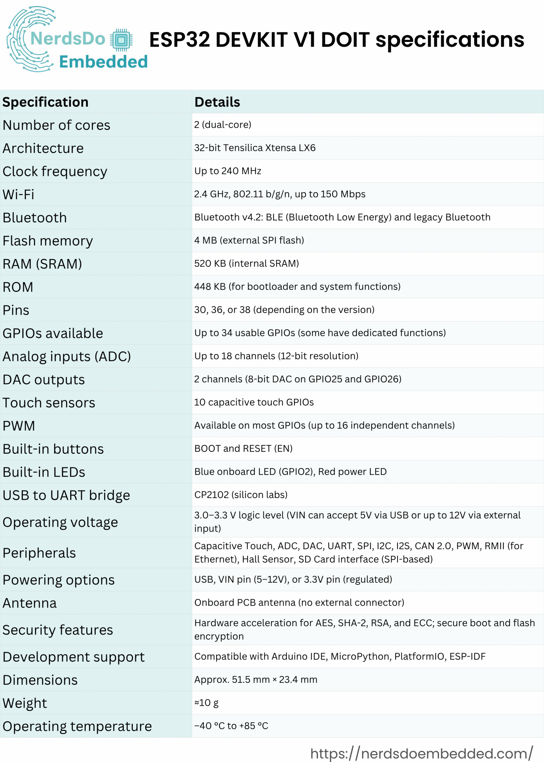
This particular ESP32 board comes with 36 pins, 18 on each side. The number of available GPIOs depends on your board model.
Here’s your enhanced and updated version of that paragraph, ready for your blog post:
The ESP32 DEVKIT V1 DOIT board comes equipped with a micro-USB interface, making it easy to connect to your computer for both powering the board and uploading code. It features the CP2102 USB-to-UART bridge chip, which allows the ESP32 to communicate with your computer over a serial COM port. Some other ESP32 boards may use a different chip like the CH340, but regardless of the chip, you’ll need to install the appropriate driver on your system so that your development environment can detect and interact with the board. We’ll cover how to install those drivers later in this guide.
In addition to the USB interface, the board includes two useful buttons:
- A RESET button (sometimes labeled as EN) to reboot the board
- A BOOT button, which is used to manually put the board into flashing mode for firmware upload. (Note: some newer boards enter flashing mode automatically and may not include a BOOT button.)
For visual feedback, the board also includes a built-in blue LED connected to GPIO2. This is especially helpful for beginners, as it allows you to test and debug your code with simple LED blink programs. There’s also a red power indicator LED that lights up when the board is powered on, confirming that it’s receiving voltage correctly.
ESP32 Pinout Reference: Complete GPIO Guide
The ESP32 chip features 48 programmable pins, each capable of serving multiple functions. However, not all of these pins are available on every ESP32 development board. For example, the popular ESP32 DEVKIT V1 DOIT board typically exposes 30 to 36 GPIOs, depending on the version. When designing or prototyping your projects, it’s important to understand which GPIOs are safe to use, which ones have specific functions, and which should be avoided.
Power Pins
Most ESP32 boards include standard power pins:
- 3V3: Regulated 3.3V output from the onboard regulator
- GND: Ground connection
- VIN: Raw input voltage (usually from USB or battery input)
You can use these pins either to power the board externally (via VIN) or to power external components like sensors or modules (via 3V3).
General Purpose Input/Output Pins (GPIOs)
Each GPIO is identified by a number (e.g., GPIO0, GPIO2, GPIO23, etc.), and that’s how you’ll refer to them in code. One of the great features of the ESP32 is pin multiplexing, which means you can assign different peripheral functions—like UART, SPI, or I2C—to most GPIOs through software configuration.
If you don’t explicitly configure the pins in code, they will use their default functions based on the boot firmware and board design. Still, understanding the recommended pin mappings and limitations can help avoid common mistakes.
Key Points to Know About ESP32 GPIOs:
- Many GPIOs are input/output capable, and some can also support analog input (ADC) or analog output (DAC).
- Certain pins are recommended for specific functions, such as:
- GPIO1 (TX0), GPIO3 (RX0): Default UART0
- GPIO5: Often used as VSPI CS0 (Chip Select)
- GPIO18, 19, 23: Typically used for SPI (CLK, MISO, MOSI)
- GPIO21, 22: Commonly used for I2C (SDA, SCL)
- Pins like GPIO0, GPIO2, and GPIO15 have special roles during boot and should be used cautiously.
- Pins with internal pull-ups/pull-downs can affect the behavior during boot and deep sleep.
Pin Behavior May Vary by Board
While the physical layout of the pins may vary between development boards (such as ESP32-WROOM-32 vs. ESP32-WROVER), the behavior of each specific GPIO number remains mostly consistent. For instance, GPIO5 is typically the SPI CS0, regardless of which ESP32 board you’re using.
Always consult the pinout diagram of your specific board and test your setup if you’re using GPIOs for specialized features.
How to Program the ESP32?
There are several ways to program the ESP32 using different programming environments and languages, including Arduino C/C++ (with the Arduino core for ESP32), MicroPython, ESP-IDF (Espressif’s official development framework), and even Lua. However, the most popular and beginner-friendly approach is using the Arduino programming language through either the Arduino IDE or Visual Studio Code with PlatformIO. For newcomers, we highly recommend starting with the Arduino IDE due to its straightforward setup, user-friendly interface, and extensive community support. In this guide, we’ll focus on programming the ESP32 using the Arduino IDE, as it offers a simple and effective development experience for building a wide range of Wi-Fi and Bluetooth-enabled IoT projects.
Programming ESP32 with Arduino IDE
To program the ESP32, you’ll need an Integrated Development Environment (IDE) where you can write, upload, and debug your code. For beginners, the Arduino IDE is highly recommended. It may not be the most feature-rich IDE, but it’s incredibly user-friendly, lightweight, and perfect for getting started. Once you’re comfortable and begin working on more advanced or larger-scale projects, you might consider switching to Visual Studio Code with the PlatformIO extension, which offers powerful features like code auto-completion, version control, and advanced project structuring.
If you’re new to the ESP32, we suggest starting with the Arduino IDE, which provides a smooth introduction to embedded programming with minimal setup.
Installing Arduino IDE
To run the Arduino IDE smoothly, your computer must have Java installed. If it’s not already installed, you can download the latest version from the official website: java.com/download.
Downloading and Installing Arduino IDE
Download Arduino IDE
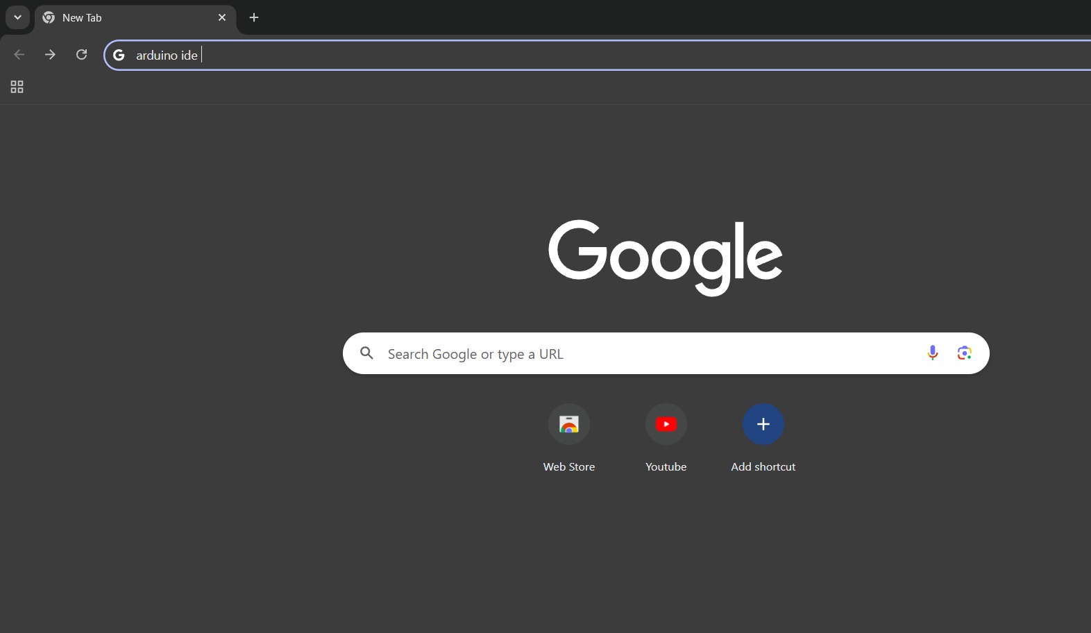
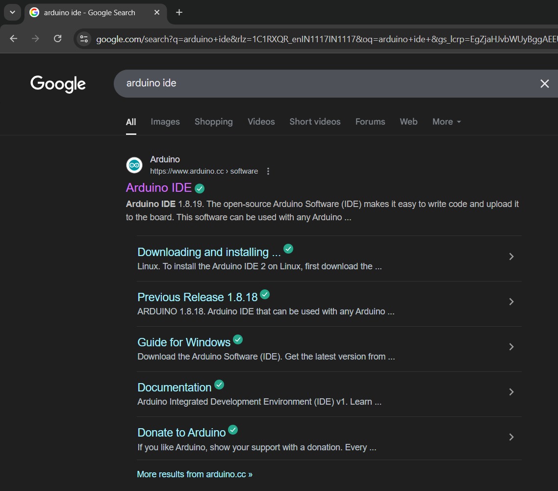
Open your web browser and search for Arduino IDE.
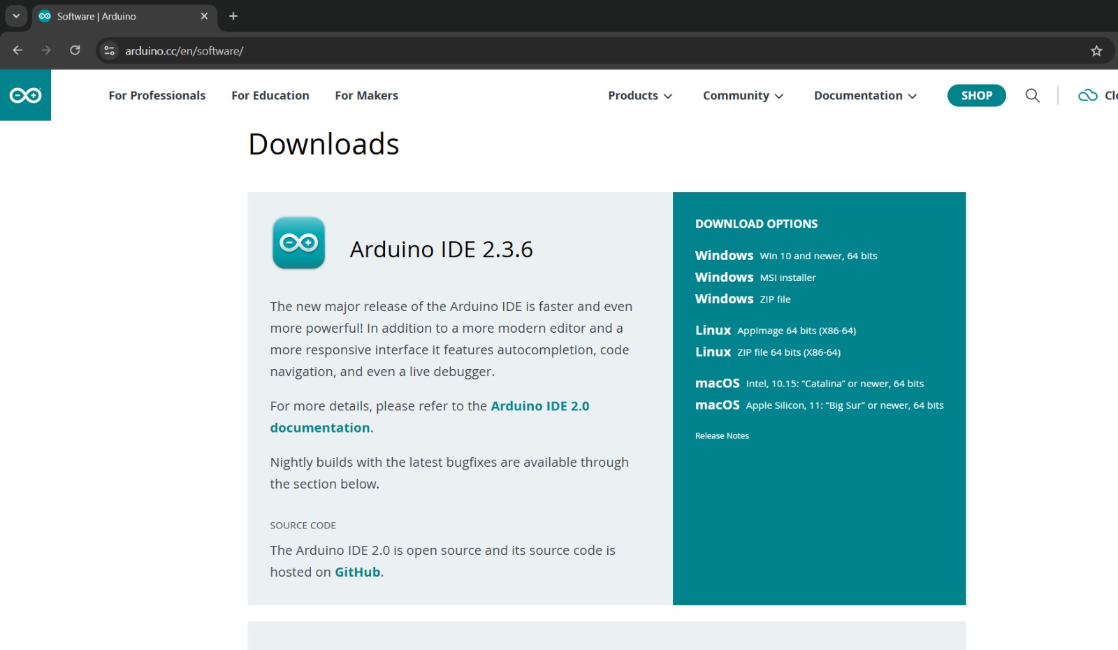
Visit the official Arduino website and navigate to the downloads page. https://www.arduino.cc/en/software/
Select the Windows 64-bit Installer.
Begin Installation
Locate the downloaded file (arduino-ide_x.x.x_Windows_64bit.exe) in your downloads folder.

Double-click the file to start the installation process.
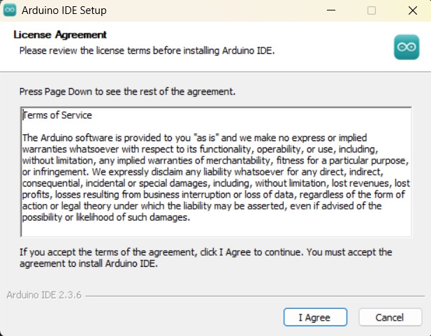
License Agreement
Read and accept the Arduino IDE license agreement by clicking “I Agree”.
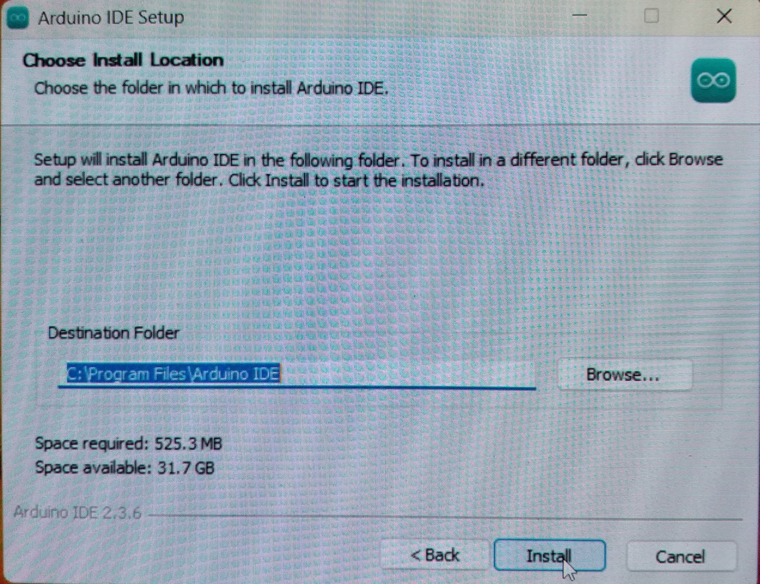
Choose Installation Folder
The default installation folder is typically C:\Program Files\Arduino IDE.
You can change this if you prefer, otherwise, click “Install”.
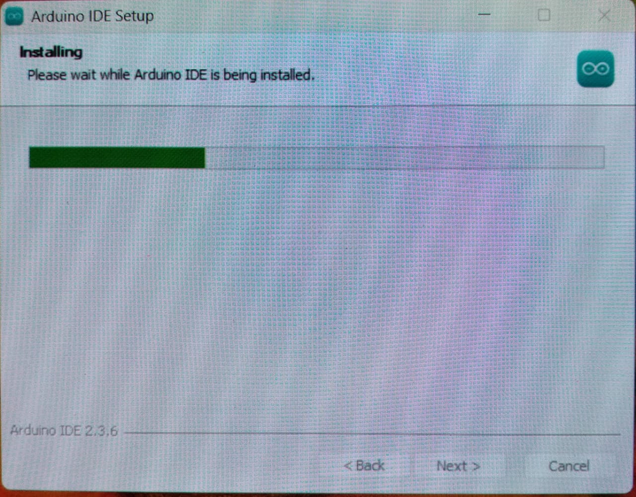
Installing Arduino IDE
Wait for the installation process to complete. This may take a few minutes.
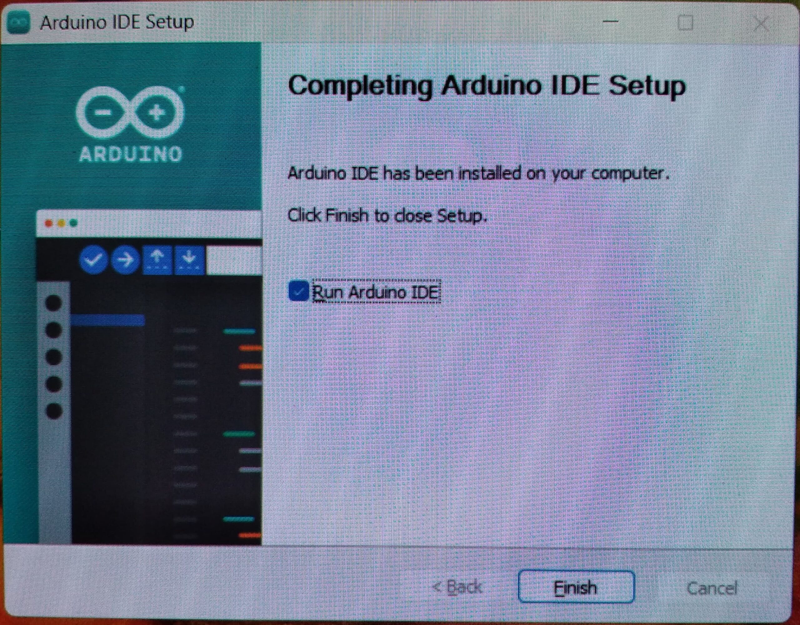
Completing Installation
After installation finishes, check the option “Run Arduino IDE” if you’d like to open it immediately.
Click “Finish” to complete the installation.
Verify Installation
Arduino IDE opens and shows an empty sketch.
Verify the IDE shows a blank template with void setup() and void loop() functions