Ready to dive into electronics? You’re in the right place! Arduino Uno is an incredibly user-friendly microcontroller board that makes it easy for beginners to experienced engineers to create interactive electronic projects.

What is Arduino Uno?
Arduino Uno is a microcontroller board based on the ATmega328P (datasheet). It has 14 digital input/output pins (of which 6 can be used as PWM outputs), 6 analog inputs, a 16 MHz quartz crystal, a USB connection, a power jack, an ICSP header, and a reset button. It contains everything needed to support the microcontroller; simply connect it to a computer with a USB cable or power it with an AC-to-DC adapter or battery to get started. You can tinker with your UNO without worrying too much about doing something wrong. The worst-case scenario is that you would have to replace the chip and start again.
Arduino Uno’s simplicity, affordability, and large supportive community make it an ideal choice for educators, hobbyists, and professionals alike who want to learn electronics and bring their innovative ideas to life.
Key Features:
- Ease of Use: Simple plug-and-play interface, ideal for beginners.
- Versatile Connectivity: Includes multiple digital I/O and analog input pins for easy integration with various components.
- Robust Community: Extensive resources, libraries, and community support are available online for quick problem-solving.
Specifications of Arduino Uno
The Arduino Uno is a powerful yet accessible microcontroller board designed around the robust ATmega328P chip. It comes packed with a range of technical specifications that allow users to easily create and prototype a vast array of interactive electronic projects.
Key Specifications:
- Microcontroller: ATmega328P
- Operating Voltage: 5V
- Input Voltage (recommended): 7-12V
- Digital I/O Pins: 14 (of which 6 provide PWM output)
- Analog Input Pins: 6
- DC Current per I/O Pin: 20 mA
- DC Current for 3.3V Pin: 50 mA
- Flash Memory: 32 KB (0.5 KB reserved by bootloader)
- SRAM: 2 KB
- EEPROM: 1 KB
- Clock Speed: 16 MHz
- Communication Interfaces: UART, SPI, I²C
- USB Connector: Standard USB Type-B
- Dimensions: 68.6 mm × 53.4 mm
- Weight: Approximately 25 g
Features of Arduino Uno
The Arduino Uno is one of the most popular microcontroller boards available today, known for its versatility, reliability, and ease of use. Whether you’re an experienced engineer or a complete beginner, the Arduino Uno offers a wide array of features that make it a go-to choice for interactive electronic projects.
Key Features of Arduino Uno:
- Microcontroller (ATmega328P)
Powered by the robust ATmega328P microcontroller, offering excellent reliability and performance for various projects. - Digital and Analog Pins
Comes with 14 digital input/output pins (6 of which support PWM output) and 6 analog input pins, providing extensive interfacing options with sensors, motors, LEDs, and more. - Plug-and-Play USB Connectivity
Integrated USB interface for easy programming and communication with computers, making it accessible even for beginners. - Multiple Power Options
Can be powered via a USB cable, external DC power adapter, or batteries, offering flexible options for various project environments. - Built-in Clock (16 MHz)
Equipped with a stable 16 MHz quartz crystal oscillator, ensuring accurate timing and performance for demanding applications. - Communication Protocols (UART, SPI, I²C)
Supports widely-used communication protocols, simplifying interactions with sensors and peripheral devices. - Reset Button and ICSP Header
Includes an onboard reset button for easy restarting and an ICSP header for direct microcontroller programming. - Open Source and Extensive Community Support
Completely open-source hardware and software with strong community backing, ensuring plenty of available tutorials, libraries, and resources.
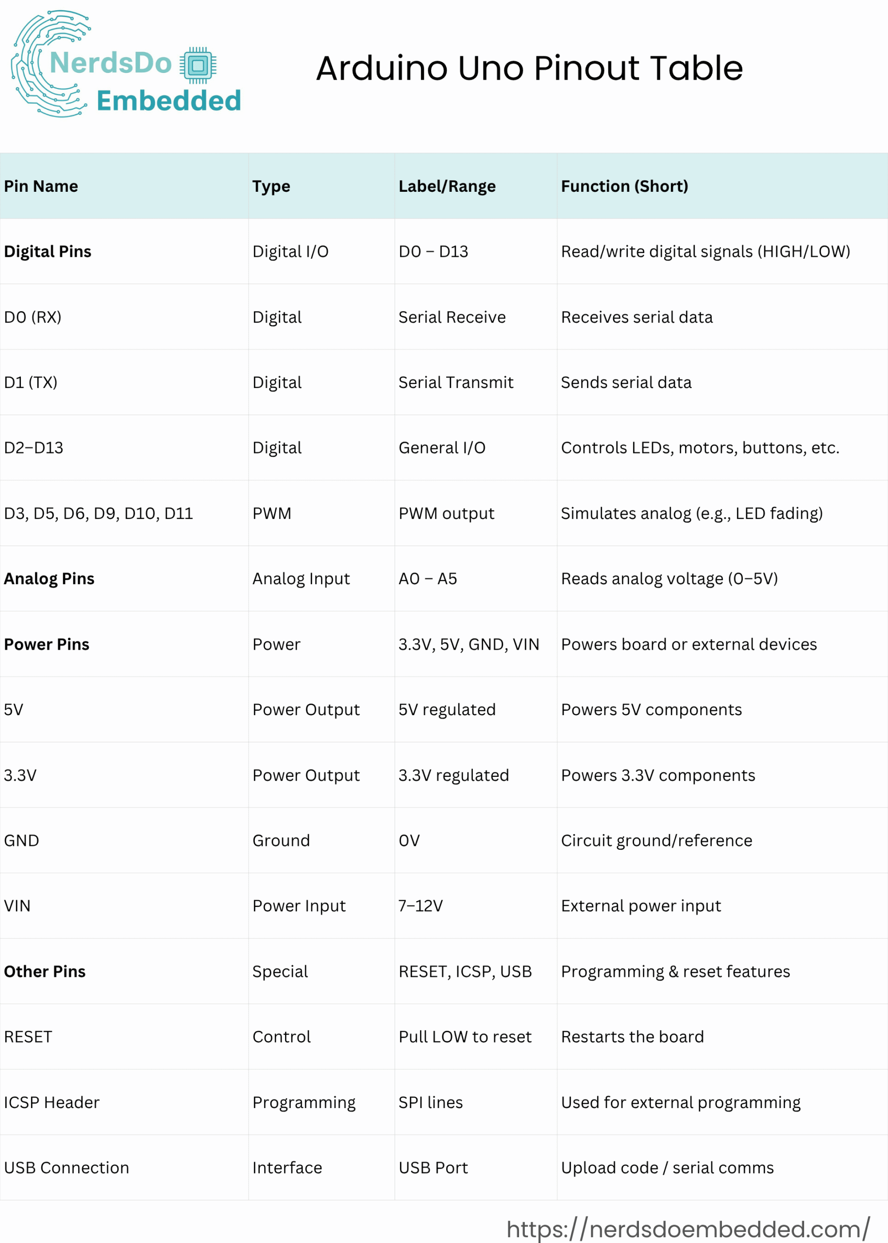
Arduino Uno Pin Diagram
The pin diagram is a visual representation of the pins on the board. It shows the location and function of each pin, making it easy to understand how the board works. The Arduino Uno board has 14 digital I/O pins, 6 analog input pins, 4 power pins, 1 reset pin, and an ICSP header. These pins allow the board to interact with sensors, actuators, and other electronic components. Below is a complete breakdown of the Arduino Uno pinout and its functions, helping you connect and configure your components correctly in any project.
Arduino Uno Digital Pins (0–13)
The Arduino Uno has 14 digital input/output pins, labeled 0 through 13. These pins are used for reading sensors, controlling outputs like LEDs and motors, and communicating with other devices. Here’s a breakdown of what each digital pin does:
- Digital Pin 0 (RX)
- Acts as the receiver of serial data.
- Used for receiving communication from other devices or your computer.
- Functions like Arduino’s “ears” listen to incoming data.
- Digital Pin 1 (TX)
- Acts as the transmitter of serial data.
- Used for sending communication to other devices or your computer.
- Functions like Arduino’s “mouth” talk or send out data.
- Digital Pins 2–13
- General-purpose digital I/O pins.
- Can be configured as either inputs or outputs.
- Use these to:
- Blink LEDs
- Control motors
- Read button or sensor signals
- Output HIGH/LOW digital signals
- Digital Pin 13 (LED Built-In)
- Internally connected to the on-board LED.
- Handy for basic testing and debugging.
- Great for running the classic “blink” program to check board functionality.
- PWM (Pulse Width Modulation):
- Some of these pins (usually 3, 5, 6, 9, 10, and 11) can do a cool trick.
- They can flicker fast between bright and dim, kind of like pretending to be sort of analog.
- This is nifty when you want to control stuff like making a light smoothly fade in and out.
- Interrupts:
- Think of these pins as the “Hey, pay attention!” crew.
- They tap your Arduino on the shoulder when something important happens, like a change in a sensor or a button being pressed.
- It’s like having a friend who grabs your attention when something interesting is going on.
- Wrap-up:
- By getting to know these digital pins, you’re opening the door to a whole bunch of creative projects.
- You can make your Arduino listen, talk, blink, and respond to the world around it in all sorts of imaginative ways!
- Interrupts:
- These pins serve as external interrupt inputs, allowing the microcontroller to respond immediately to specific events or signal changes.
- They tap your Arduino on the shoulder when something important happens, like a change in a sensor or a button being pressed.
- It’s like having a friend who grabs your attention when something interesting is going on.
Arduino Uno Analog Pins
Analog pins on the Arduino Uno are used to connect analog sensors and signals. Unlike digital pins, which can only be HIGH or LOW, analog pins can read a range of voltage levels, making them perfect for sensors that output varying signals.
- Purpose:
- Ideal for reading data from light sensors, temperature sensors, potentiometers, and other analog devices.
- Number of Pins:
- The Arduino Uno includes six analog input pins, labeled A0 to A5.
- Voltage Range:
- These pins can read analog voltages from 0 to 5 volts.
- Resolution:
- Each analog pin has a 10-bit resolution, which means:
- The voltage range (0–5V) is divided into 1024 discrete levels.
- Allows for precise analog measurements.
- Each analog pin has a 10-bit resolution, which means:
Pin-by-Pin Breakdown:
- Analog Pin A0:
- Can read an analog voltage and convert it into a digital value.
- With 10-bit resolution, it can distinguish between 1024 different voltage levels between 0 and 5 volts.
- Analog Pin A1:
- Similar to A0, this pin has a 10-bit resolution.
- Used to read varying analog signals.
- Analog Pin A2:
- Just like A0 and A1, A2 can read analog signals.
- Has a 10-bit resolution for precise measurements.
- Analog Pin A3:
- It functions the same as other analog pins.
- Reads analog voltages with a 10-bit resolution.
- Analog Pin A4:
- Works just like the other analog pins.
- Allows analog voltage reading with 10-bit resolution.
- Analog Pin A5:
- Similar to the rest, A5 reads analog signals.
- Also provides a 10-bit resolution for accurate input readings.
Arduino Uno Power Pins
The Arduino Uno has several power pins used to power the board and other connected devices. Below is a breakdown of what each power pin does:
- 5V Pin:
- Provides a regulated 5V DC output.
- Can be used to power other devices that require 5V DC.
- 3.3V Pin:
- Provides a regulated 3.3V DC output.
- Can be used to power devices that require 3.3V DC.
- GND Pins (Ground):
- Used to connect the board to the ground.
- Helps complete electrical circuits and provides a reference voltage.
- VIN Pin:
- Used to power the board using an external power source.
- Can accept a voltage between 7V and 12V DC.
Other Pins of Arduino Uno
The Arduino Uno has several other pins used for specific purposes. Here is a breakdown of what each one does:
- Reset Pin:
- Used to reset the board.
- When this pin is set to LOW, the Arduino board resets.
- ICSP Header:
- Stands for In-Circuit Serial Programming header.
- Used to program the board using an external programmer.
- USB Connection:
- Used to program the board and to communicate with other devices via USB.
Arduino Uno Input and Output
The Arduino Uno, built around the ATmega328P microcontroller, offers robust capabilities for interfacing with various devices through its versatile input and output (I/O) pins. This guide delves deep into how these pins can be utilized effectively in your projects, detailing their functionalities and communication capabilities.
Understanding Digital Pins
The Arduino Uno features 14 digital pins labeled 0 to 13, each capable of input and output operations.
Digital Input
Digital pins, when configured as inputs, can detect binary states:
- HIGH (5V): Represents an active or “on” state.
- LOW (0V): Represents an inactive or “off” state.
These pins commonly interface with:
- Pushbuttons
- Toggle switches
- Digital sensors like PIR motion detectors or proximity switches
Example of Digital Input:
pinMode(2, INPUT_PULLUP);  // Activate internal pull-up resistor
int buttonState = digitalRead(2);  // Read the state of pin 2
Digital Output
When set as outputs, digital pins control devices by sending HIGH or LOW signals, which can drive:
- LEDs
- Relays
- Motors
- Buzzers
Pins 3, 5, 6, 9, 10, and 11 support PWM (Pulse Width Modulation), suitable for analog-like control such as dimming lights or regulating motor speeds.
Example of Digital Output:
pinMode(13, OUTPUT);
digitalWrite(13, HIGH);  // Turn LED on

// PWM example for dimming an LED
analogWrite(9, 128);  // 50% brightness
Exploring Analog Pins
The Arduino Uno includes 6 analog input pins labeled A0 to A5.
Analog Input
Analog pins read continuous voltage signals ranging from 0V to 5V and convert these into a digital format with a resolution of 10 bits (0–1023). These pins are ideal for:
- Potentiometers
- Temperature sensors
- Light-dependent resistors (LDRs)
Example of Analog Input:
int sensorValue = analogRead(A0);
float voltage = sensorValue * (5.0 / 1023.0);  // Convert ADC reading to voltage
Analog Output via PWM
Though the Uno lacks true analog output, PWM pins simulate analog voltage effectively.
Example of PWM Usage:
analogWrite(6, 200); // Controls brightness or motor speedUsing Arduino Uno Pins for Communication (Input and Output)
The Arduino Uno supports multiple communication methods essential for interfacing its I/O pins with advanced modules and peripherals:
UART (Universal Asynchronous Receiver-Transmitter) – Input and Output
- Pins: 0 (RX – input) and 1 (TX – output)
- Purpose: Serial communication for debugging or data exchange.
- Use cases: Communicating with PCs, Bluetooth modules, and GPS modules.
UART Example:
Serial.begin(9600); // Start serial communication at 9600 baud
Serial.println("Hello, World!"); // Send data to the serial monitor
SPI (Serial Peripheral Interface) – Input and Output
- Pins: 10 (SS – output), 11 (MOSI – output), 12 (MISO – input), 13 (SCK – output)
- Purpose: Fast, synchronous communication protocol
- Use cases: Interfacing with RFID modules, SD card readers, and displays.
SPI Example:
#include <SPI.h>
SPI.begin();
// Sending data
SPI.transfer(0x45);
I2C (Inter-Integrated Circuit) – Input and Output
- Pins: A4 (SDA – data line, input/output), A5 (SCL – clock line, output)
- Purpose: Multi-device, two-wire communication
- Use cases: Sensors, RTC modules, OLED and LCD displays
I2C Example:
#include <Wire.h>
Wire.begin();
Wire.beginTransmission(0x68); // Device address
Wire.write(0x00);  // Register address
Wire.endTransmission();
Special Purpose Pins
- AREF: Sets custom voltage reference for analog inputs.
- Reset: Resets the board when pulled LOW.
Practical Tips for Using Arduino Pins
- Leverage internal pull-up resistors to simplify circuits.
- Clearly define pin modes in the
setup()function. - Avoid using pins 0 and 1 for general digital I/O if Serial communication is required.
FAQs
1. What are the key features of the Arduino Uno?
The Arduino Uno features an ATmega328P microcontroller, 14 digital I/O pins (6 of which support PWM), 6 analog input pins, a 16 MHz quartz crystal, USB connection, power jack, ICSP header, and a reset button.
2. What is the operating voltage and input voltage range of Arduino Uno?
The operating voltage is 5V. The recommended input voltage range is between 7V to 12V. Input voltage beyond this range might damage the board.
3. How many analog and digital pins does Arduino Uno have?
The Arduino Uno provides 14 digital pins (0–13) and 6 analog pins (A0–A5). Digital pins can be set as input or output, while analog pins read variable voltage inputs.
4. Can Arduino Uno pins supply power directly to sensors and actuators?
Yes, but there’s a limitation. Each digital pin can provide or draw up to 40mA. The total current drawn from all pins should not exceed 200mA. For higher power loads, external transistors or relays should be used.
5. Which pins support PWM (Pulse Width Modulation) on the Arduino Uno?
PWM pins on the Arduino Uno are pins 3, 5, 6, 9, 10, and 11. These pins simulate analog voltage control, making them ideal for applications like dimming LEDs or controlling motor speeds.